Remote Portal Guide
📚 Overview:
.PNG-,Video%20Security%20Client,-Video%20Security%20Client)
1. Introduction
The Remote Portal is part of Bosch’s Cloud-based Services and supports plug-and-play remote access and services via the cloud. Services are provided via the Remote Portal’s browser interfaces or as part of domain-specific applications or solutions.
Below is a short overview of features and services provided by the Remote Portal. More details can be found in the respective sections of this documentation.
Getting started
Registration at the Remote Portal and use of Remote Portal features are free of charge. For typical use one account should be created per company. Managing additional users and controlling access is then done using Remote Portal features described below.
Some services described below may require licenses for activation.
Supported devices
Remote Portal supports the following devices:
Device type | Devices |
|---|---|
Intrusion alarm system | B- and G-series |
Video system | DIVAR IP all-in-one 4000 DIVAR IP all-in-one 5000 DIVAR IP all-in-one 6000 DIVAR IP all-in-one 7000 (DIP-72, DIP-73, DIP-74) IP cameras |
Remote Portal features
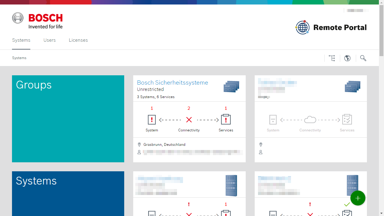
System hierarchy
Remote Portal allows freely grouping systems and nesting groups of groups. This allows to define a hierarchy for devices, e.g. by customer or installation location, limit access for a set of devices or aggregate status of multiple devices.
User and access management
Remote Portal allow fine-grained control to the portal and access to devices and services by means of additional users and association of these users with systems, groups of systems and services.
Health monitoring
The Remote Portal provides various health checks on devices registered to the portal, including status of connection device-cloud and device functionality. The Remote Alert services allow sending notifications to one or more users when health issues arise.
Services
Remote Connect
Remote Connect allows connecting devices to the Remote Portal and is required for access via client software or use of further services. In order to connect a device to the Remote Portal, please refer to the individual device documentation. In most cases, it is required to initially connect the device to the cloud via on-site configuration.
Licensing of Remote Connect varies by product, see licensing for details. For IP cameras, Remote Connect allows to remotely configure the IP camera using the Configuration Manager Client Software.
Remote Alert
Remote Alert monitors system health and allows sending of notifications (SMS, E-mail) to users based on various triggers.
Remote Alert is available as part of Remote Connect service.
Remote Maintenance
Remote Maintenance assists in performing maintenance tasks on compatible devices and systems. Remote Maintenance is currently available for FPA-5000, for additional details please also visit http://www.boschsecurity.com/remoteservice-fire/.
Remote Maintenance is available as part of the Fire Remote Service license bundle, for details see licenses.
Camera Counter Reports
Camera Counter Reports are available on IP cameras capable of essential or intelligent video analytics connected directly to the Remote Portal. Camera Counter Reports poll counters from one or more cameras and store their values for up to 30 days.
The stored data can be visualized in the Remote Portal, accessed via API or exports as CSV data for further processing.
Camera Counter Reports are licensed with a 1-year license, see licensing for details.
2. System requirements
Browsers
The browser-based interfaces of Remote Portal are best viewed with a modern browser such as Firefox, Chrome or Internet Explorer. JavaScript must be enabled.
Device firmware support
To utilize all features and services of the Remote Portal the following firmware versions (or later) are recommended:
Intrusion System | Video System | ||
|---|---|---|---|
Device | Min. firmware | Device | Min. firmware |
B-/G-Series | 3.02 | DIVAR IP all-in-one | 7000 (DIP-73xx) DIVAR IP System Manager 2.0 |
IP cameras | 6.5 | ||
Client software
Compatible client software can establish device connections using Remote Portal credentials and via Internet. Local access to devices remains unaffected. The following client software versions (or later) are recommended.
Intrusion Alarm System | Video System | |||
|---|---|---|---|---|
Client | Min. version | Client | Version | Device Support |
RPS | 6.02 | Web-interface | Up-to-date version of:
The Bosch Video SDK for configuring VCA can be used with Internet Explorer 11 and Firefox ESR 45.8. For advanced configuration please use Configuration Manager. |
|
RSC (iOS, Android) | 2.7 | Video Security Client (1) | 3.5.4 |
|
Video Security App (1) | 3.5.4 |
| ||
To connect using Remote Portal Video System clients must have access to the following ports: | ||||
(1) Compatibility update for IP cameras planned 2017
Internet connection
Use of Remote Portal services requires the following Internet access for devices. Please make sure that appropriate bandwidth is available:
Source | Destination (domain name) | Destination (IP address) | Description |
|---|---|---|---|
On-site cameras | Cloud Connector (camera firmware >= 6.40 without device certificate) | ||
On-site cameras | Cloud Connector (camera firmware >= 6.40 with device certificate) | ||
On-site cameras | Certificate Revocation List (CRL) | ||
On-site cameras | Remote Portal Endpoint | ||
On-site cameras | Video Relay | ||
On-site cameras | Video Relay | ||
On-site cameras | Video Relay | ||
On-site cameras | Video Relay | ||
On-site cameras | Video Relay | ||
On-site cameras | Time server to be used by Remote Portal (Video Relay) | ||
On-site cameras | Time server to be used by Remote Portal (Video Relay) | ||
On-site cameras | Time server to be used by Remote Portal (Video Relay) | ||
On-site cameras | Time server to be used by Remote Portal (Video Relay) | ||
On-site cameras | Time server to be used by Remote Portal (Video Relay) | ||
Remote System Management Devices | 52.29.189.224 | REST API for device provisioning | |
Remote System Management Devices | Download of software artefacts, upload of log files | ||
Remote System Management Devices | tls://a1j83emmuys8gs-ats.iot.eu-central-1.amazonaws.com:8883 | Device communication for telemetry, events, commands | |
B-/G-Series (Intrusion) | Local IP via DHCP or static assignment | ||
B-/G-Series (Intrusion) | Access to public Internet on port 443. |
3. Portal guide
System hierarchy
To facilitate management of larger number of systems and allow fine-grained access control to these systems the Remote Portal provides a simple but powerful grouping mechanism. Grouping can be done by administrators of the account and provides the following functionality explained in greater detail below:
Defining a system hierarchy
Limiting access to groups and systems
Aggregating status information of contained systems and groups
Info
We recommend to create individual accounts (identifiable by Remote ID) for each end-customer. This improves structure and has benefits for managing accounts and licenses.
System hierarchy
The system hierarchy of the Remote Portal allows systems and groups to reside either at the top level of the hierarchy or nested in one or more groups below. There is no limit to the the depth of the nesting or combination of elements at any level.
The Remote Portal displays the hierarchy as a tree structure (giving access to the whole hierarchy, shown on left of screen) and by displaying the system and group cards of the current level on the right-hand side of the screen. Use the tree to navigate to any group or level of the hierarchy and cards to drill down in the hierarchy from current level.
Info
The tree display can be toggled by clicking on the tree symbol in the navigation toolbar above the main content area.
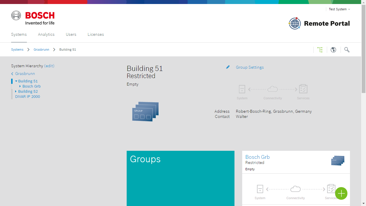
The system hierarchy can be edited by selecting "edit" in the tree navigation area. This function is available to administrators of the portal only.
With edit mode active elements of the tree can be rearranged in the existing group hierarchy. New groups can be added for a selected level by selecting the green "+" button and providing basic information for this group. This information can be updated by selecting "Group settings" at any later point in time.
Access control
By default any system within the Remote Portal can be accessed by administrators or technicians via browser or programming software. Access for customers must be granted explicitly.
Customizing technician access
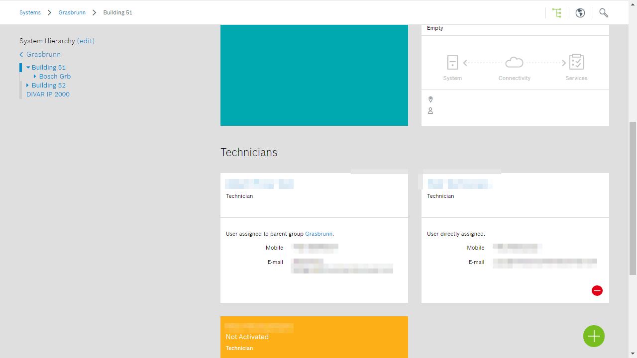
Technician access can be customized by system or for a set of systems by adding a "Technician" account to a system or group respectively. This also automatically removes unrestricted access to these systems and groups. Unlimited access is restored again when all technicians are removed from a system and group.
For details on the permissions technician access grants see the users section of this document.
Granting access
Adding a technician to a group grants access to all systems of this group and the systems of any nested group. Access rights accumulate from top to bottom of the hierarchy, explained by this example:
|
For this example technicians A and B can access systems 1-1, 1-2, 2-1 and 2-2, whereas technician C can only access systems 2-1 and 2-2 and technician D only systems 2-2.
Resulting access rights are shown at every level, as an example system 2-2 would all technicians having access, matching the example's configuration.
Removing access
Removal of access can be only be done at the highest level that a particular technician has access. In the example, access for technician A would need to be removed at group 1's level, though the technician is also shown in lower levels. Removal of access, where applicable, is shown via a red "-" button.
Note
Removal of the last "Technician" account at a particular level will reinstate unrestricted access of all technicians.
Status aggregation
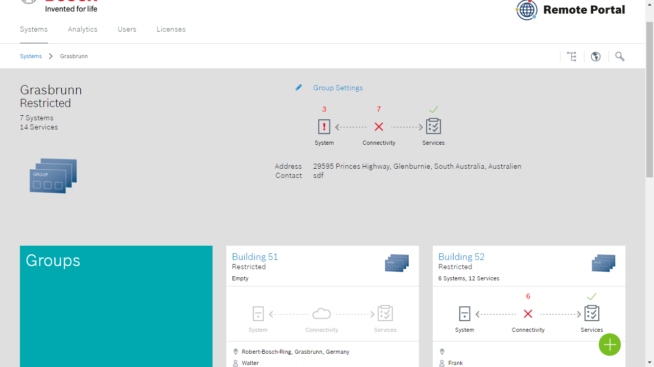
Nesting systems in a group hierarchy leads to aggregation of status information of all the systems within a group, independent of nesting level. A group always displays the aggregate status of all systems (in particular system health, connectivity status or service status), with trouble states "bubbling" up to the top of group and displayed using the status icons. This provides a quick way to verify health of a large number of systems contained in a group and in case of error drilling down to affected systems by clicking through cards displaying active trouble states.
Users
Overview
The Remote Portal provides three different user types with which you can control access and use of portal and connected devices.
Administrators
"Administrators" accounts have full access to all features of the portal. Typically there will be only a select number of administrators to perform tasks such as adding new users, activating services or changing access rights on systems.
Technicians
"Technicians" account are used to perform tasks such as adding new devices, performing remote configuration or system maintenance. Technicians will use the Remote Portal and client software such as RPS.
Technicians can be granted explicit permission to also manage Software Licenses for example for Software Products such as BVMS or IVA Pro.
Customers
"Customers" are typically accounts created for end customers. Customers typically will use client software, such as the video security app, to connect and use devices or can be created as users which receive notifications via SMS and Email.
More detailed comparison of the different users can be found in the table below:
User type | Portal use | Device use | Service use | |
|---|---|---|---|---|
Video System | Intrusion Alarm System | |||
Administator |
|
|
|
|
Technician |
|
|
| (After access granted by administrator)
|
Customer |
|
|
|
|
All users |
|
| ||
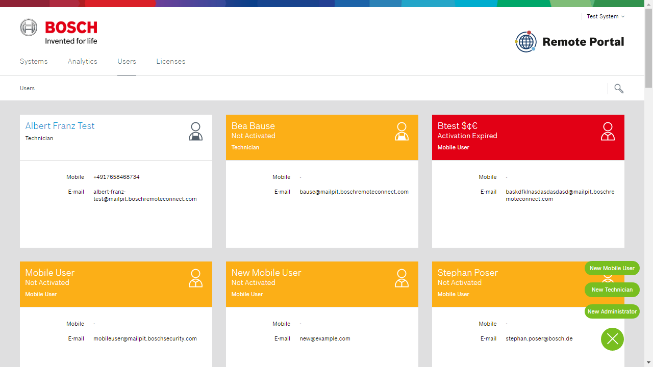
Managing users
Users are managed by selecting the "Users" tab from the top navigation bar. From there you can add, edit and remove user accounts and get an overview of a user's access to systems and services.
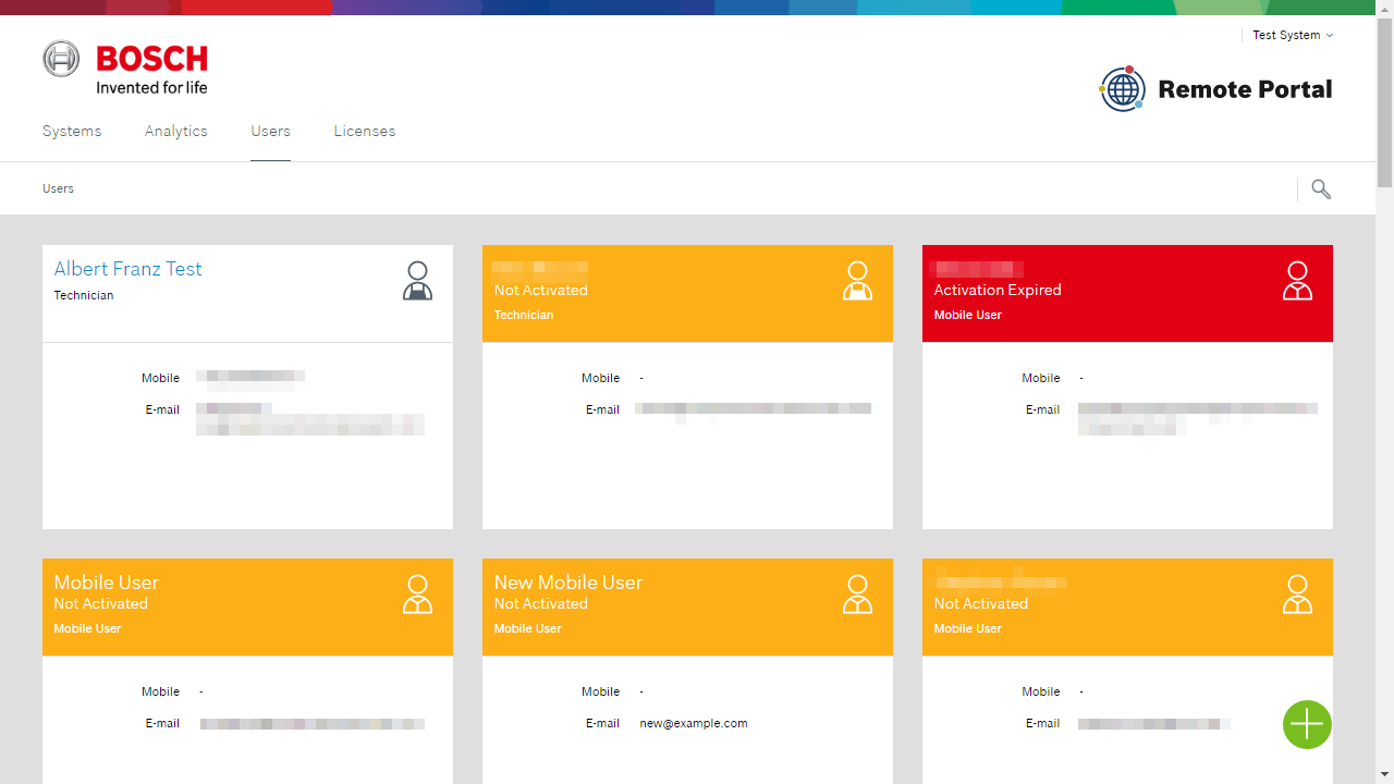
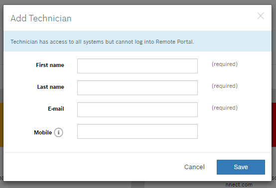
Adding users
To add users select the "Users" tab in the top navigation bar, select the green "+" button and choose the type of user you wish to add. See the table above for an explanation of user types.
Provide a basic set of information for the user you are creating and click "Save":
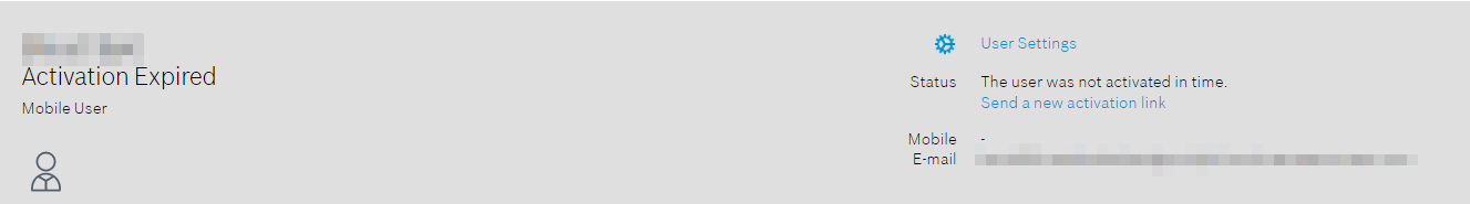
Newly created users receive an automated email from the system to confirm email address and set a custom password. Until this step has been taken by the user the user is in "Not activated" state and is highlight in yellow on the Users overview page. The activation link is valid for ten days, if a user does not confirm the email address within that time frame the link will expire and the the user is shown highlighted in red. You can request a new link to be sent for this user by clicking on the user's card and from there clicking on "Send a new activation link".
Until a user's email is verified the user cannot login to the Remote Portal. However a user's account can be seen and, for example, assigned to devices.
Editing users
User information (name, email address and mobile phone number) can be edited by selecting a user's card and clicking on "User Settings".
Note
Changing email address is done immediately and may disrupt existing logins from client software, e.g. RPS
Deleting users
Users can be deleted by selecting the user's card and clicking on "User Settings". Select "Delete" and confirm by selecting "Delete" again.
Deleted users are deleted immediately and cannot be recovered. Any access to devices or the portal associated with this user is revoked immediately.
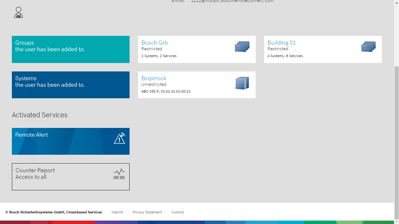
Reviewing access to systems and services
Select a user's card to review access to systems and services.
Groups and Systems
The groups and systems section shows all groups and systems to which a user has been granted access. To modify access rights, select the respective group or system and remove the user from there.
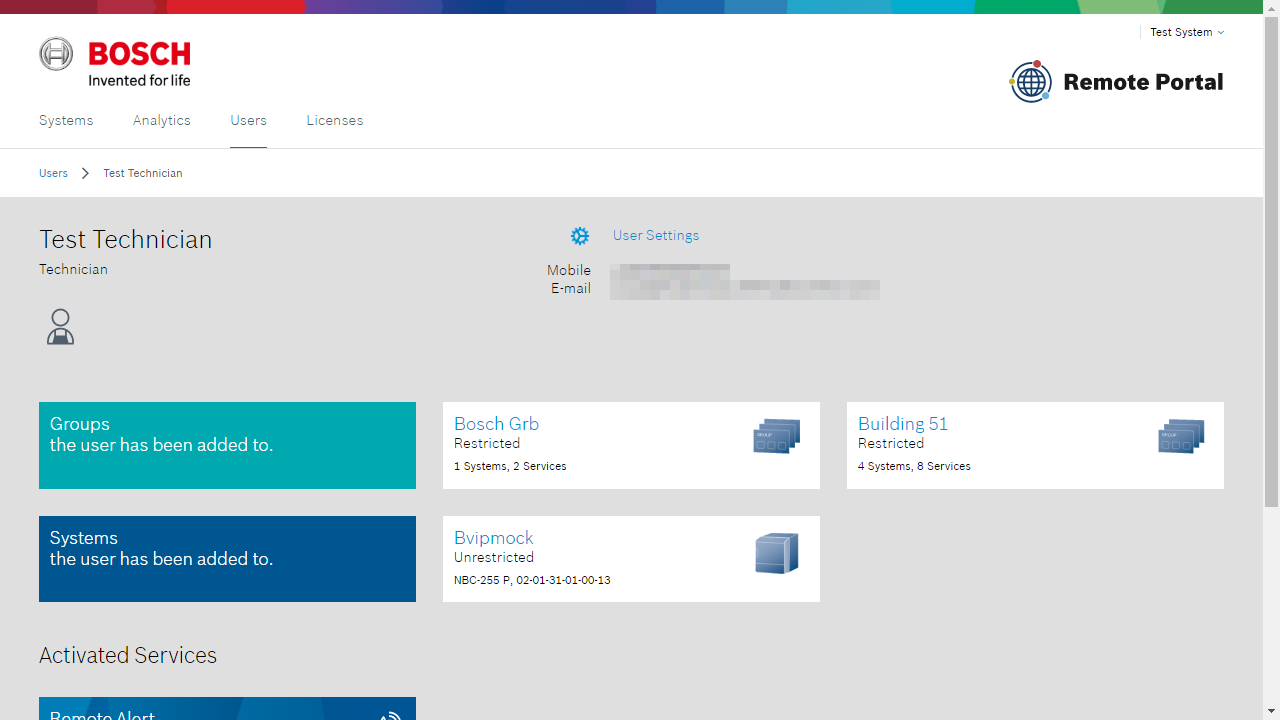
Services
The services section lists all services that a user has access to and can utilize. To manage, as with Systems and Groups, click on the respective service and edit the user's settings as desired.
Note
Access to services is tied to access to a system. As an example a technician granted access use of "Remote Maintenance" service may also use the "Remote Connect" service. Verify the right user type is used grant only desired access rights to a system.
Licenses
The table gives a high-level overview of functionality available without licenses vs. services requiring licenses and activation:
Domain | Device | Service | Licensing |
|---|---|---|---|
Intrusion | B-/G-Series | Remote Connect | As part of intrusion installer services, |
Video | DIVAR IP all-in-one | Remote Alert | Included with device purchase |
DIVAR IP all-in-one | Remote System Management | Purchase of 1 year license | |
IP cameras | Remote Connect for Remote Configuration | Included with device purchase | |
Remote Alert | Included with device purchase | ||
VideoView+ | Purchase of 1, 3, 5-year licenses | ||
Cloud Storage | Purchase of 1 year license | ||
Camera counter reports | Purchase of 1 year license | ||
Alarm Management | Purchase of 1 year license | ||
Alarm Verification | Purchase of 1 year license | ||
VMS (Milestone XProtect) | Alarm Verification | Purchase of 1 year license |
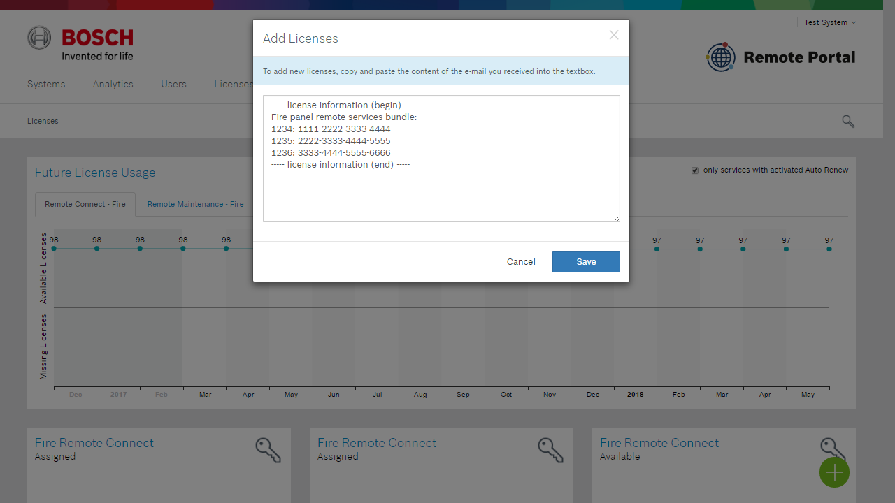
Ordering licenses
Dedicated licenses are ordered via a standard sales order to Bosch. Once order processing is completed a 16-digit license key is returned to the purchasing contact via email for each license order. This example shows an order of the FPA-5000 Remote Services license bundle licenses:
Dear customer,
please follow the steps below to add your recently purchased licenses to your account:
Log into your account at https://remote.boschsecurity.com
Click the "Licenses" tab in the top bar.
Click the "Add Licenses" button.
Copy and paste the entire license information between the dashed lines to the browser dialog box and click "Add".
----- license information (begin) -----
Fire panel remote services bundle:
1234: 1111-2222-3333-4444
1235: 2222-3333-4444-55551236: 3333-4444-5555-6666
----- license information (end) -----
Thank you for using Remote Services.
Regards,
Bosch Security Systems
Adding licenses
Licenses must be added to a Remote Portal account before being ready for use. This is done by selecting the "License" tab, which is available for any administrator logged into the Remote Portal:

To add licenses to the active account select the green "+" button and copy and paste the license information provided into the presented dialog.
Note: The Remote Portal intelligently parses out licenses information from the information entered in the dialog, it is not necessary to apply special formatting or remove extra text. Multiple license codes can be added at once.
Licenses added are saved in the Remote Portal for use, but only consumed when the corresponding is activated (manually or via auto-renewal). This allows having a stock of licenses in the Remote Portal for immediate use, without inactive licenses expiring inadvertently.
Using licenses / activating services
Subscribing to a service on device checks for availability of a suitable license in the Remote Portal account and converts if from an available license to a license subscribed to a device. License are assigned at random from stock available, a particular license's assignment can be checked from the license.
Remaining life-time of a license assigned to a service is shown in the service section of a device. Once the license expires the service is no longer available for use. License expiration is highlight in red in a device's service section and the systems overview screen at the services icon:
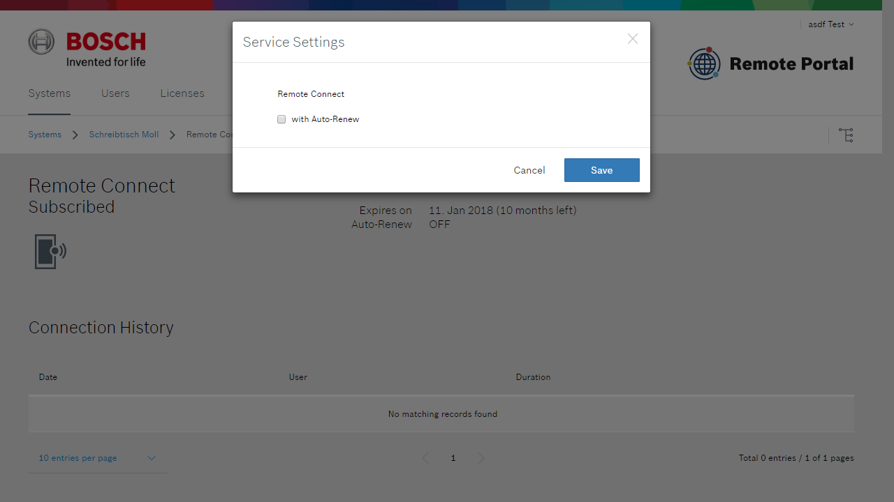
Auto-renewal
For convenience and to avoid service interruptions, services can be configured to auto-renew upon expiry. This can be done at time of service subscription or the service settings screen for a particular service:
Auto-renewal requires a license to be available when renewal is due, otherwise renewal fails. Use the license management feature to plan for your license needs at regular intervals.
Managing licenses
The licenses tab provides the following information and actions to manage licenses:
Future License Usage
At the top of the screen current and predicted license usage is displayed, broken down by service / license type:
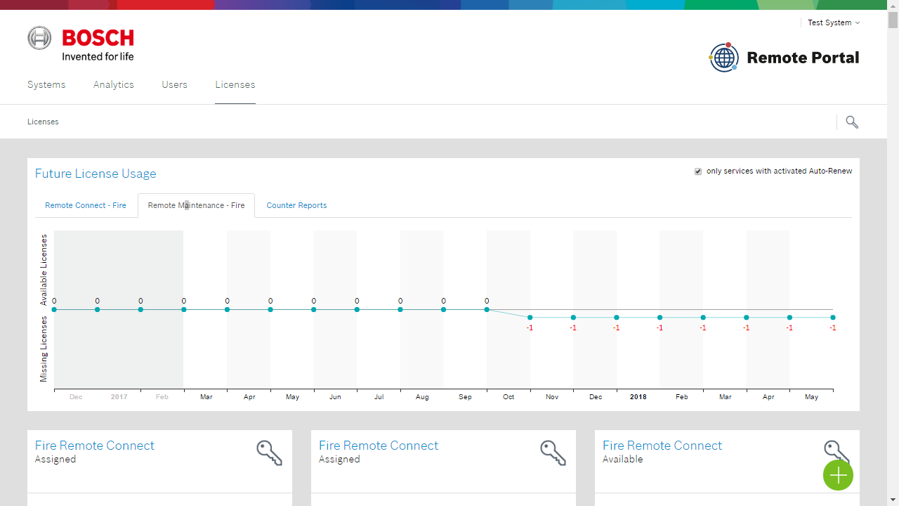
Based on the number of device subscribed, remaining lifetime of subscription and auto-renewal of service subscriptions the Remote Portal predicts when additional service licenses are needed, marking the estimated demand of licenses in red. Note that this estimation will change when additional devices are subscribed to a service.
Individual license status and maintenance
Individual licenses are shown below the license usage section of the screen and provide information on each purchased license:
Status: available, assigned, expired
For assigned licenses: Validity and assigned system
License that have not been assigned to a system yet (are in available state) can be removed from an account by clicking the trashcan symbol of the license. This allows you to transfer licenses to another account or make licenses unavailable for use.
Warning
License deletion is immediate and permanent. You must copy and save the license key presented in the warning dialog for later use.
Health information
At the moment the following health information are provided
Device Type | Information |
|---|---|
Camera | Recording Error (Stream 1) Recording Error (Stream 2) Recording Error (Stream 1 & 2) Firmware Level Device On/Offline (Debounce time approx. 5 minutes) |
DivarIP | Insufficient space on system partition Space on system partition could not be determined At least one target is offline Insufficient storage available in the system At least one device is offline At least one camera does not record At least one harddisk should be exchanged, as it is not at 100% health Watchdog Service is offline Disk Management Service is offline At least one disk is not recognized anymore Fan speed is critical Storage is formatted or reconfigured or a raid repair is in progress |
Camera connectivity troubleshooting
Please follow below list to troubleshoot connectivity issues during commissioning cameras to Bosch Remote Portal.
Camera configuration
Time Server
Navigate to General > Date/Time and configure the Time server address as follows:
ntp-us.cbs.boschsecurity.com (for Americas) or
ntp-eu.cbs.boschsecurity.com (for Europe and rest of the world) or
VRM IP address (when recording on VRM based recorder, e.g. Divar IP)
Note: Make sure that the configured date does not deviate from the actual date.
Network
Navigate to Network > Network Access
Set DHCP to On
If DHCP needs to be off on customer request > configure correct Gateway and DNS server addresses
Navigate to Network > Advanced
Set the Cloud-based services Operation to On and click Set
Cloud Connectivity
Navigate to Service > System Overview
Check Cloud State > should be ‘Ready for cloud service‘
If Cloud State is different from ‘Ready for cloud service‘:
verify Internet connection according to below troubleshooting guide.
Connectivity Troubleshooting
For troubleshooting perform the following steps:
Please check if the camera is connected to the Internet and can reach the Cloud-based Services system.
In the local network open the IP camera's website, navigate to SETTINGS > Advanced Mode > Service > System Overview
Check the ‘Cloud state’:
Expected state: „Ready for cloud service”
Error states | Cause | Solution |
|---|---|---|
“Trying to connect...” | Trying to establish a TCP connection. | Check the Internet connection *, reset the camera ** |
“Trying to connect... (Server not reachable)“ | DNS resolution did not work on last connection trial. | Check the Internet connection *, check the router’s gateway settings. |
“Trying to connect... (Server not responding)” | TCP connection has been timed out on last connection trial. | Check the Internet connection *, check the router’s gateway settings. |
“Not running” | Cloud-based Services 'Operation' mode is “off”. *** | Set Cloud-based Services 'Operation' mode to “on”, power-cycle the camera. |
“Not running (DHCP not active)” | Cloud-based Services 'Operation' mode is “auto”, DHCP is disabled or did not get an IP address. | Enable DHCP, check if a DHCP server in the LAN provides a valid IP address to the camera. |
“Not running (no connection to server)” | Cloud-based Services 'Operation' mode is “auto”, max connection trials exceeded. | Check the Internet connection *, check the router’s gateway settings, power-cycle the camera. |
“Not running (Device not added to CBS system)” | Cloud-based Services 'Operation' mode is “auto”, max connection duration timed out (8 hours). | Power-cycle the camera. |
* Check that the router does not block outgoing traffic on port 42000.
** Reset the camera with reset button (press button for 7 secs until the LED turns red). After the LED is green try again to add the camera to the cloud.
*** Cloud-based Services 'Operations' mode can be found on the IP camera's website > SETTINGS > Advanced Mode > Network > Advanced > 'Cloud-based services'.
Ports, Domain Names and IP addresses
„The following domain names must be reachable from the cameras on customer’s site.
„DNS needs to be activated so that cameras can connect to the hosts specified below.
„In case no DNS server is available column “Destination (IP address)” shows the IP addresses to be used.
Note that the IP addresses might change, only domain names stay fix.
Source | Destination (domain name) | Destination (IP address) | Description |
|---|---|---|---|
On-site cameras | Cloud Connector (camera firmware >= 6.40 without device certificate) | ||
On-site cameras | Cloud Connector (camera firmware >= 6.40 with device certificate) | ||
On-site cameras | Certificate Revocation List (CRL) | ||
On-site cameras | Remote Portal Endpoint | ||
On-site cameras | Video Relay | ||
On-site cameras | Video Relay | ||
On-site cameras | Video Relay | ||
On-site cameras | Video Relay | ||
On-site cameras | Video Relay | ||
On-site cameras | Time server to be used by Remote Portal (Video Relay) | ||
On-site cameras | Time server to be used by Remote Portal (Video Relay) | ||
On-site cameras | Time server to be used by Remote Portal (Video Relay) | ||
On-site cameras | Time server to be used by Remote Portal (Video Relay) | ||
On-site cameras | Time server to be used by Remote Portal (Video Relay) | ||
Remote System Management Devices | 52.29.189.224 | REST API for device provisioning | |
Remote System Management Devices | Download of software artefacts, upload of log files | ||
Remote System Management Devices | tls://a1j83emmuys8gs-ats.iot.eu-central-1.amazonaws.com:8883 | Device communication for telemetry, events, commands |
Note:
If above steps do not succeed to connect the IP camera to the Security Cloud, please contact support.security-cloud@bosch.com
4. Service guide
Remote Connect
General
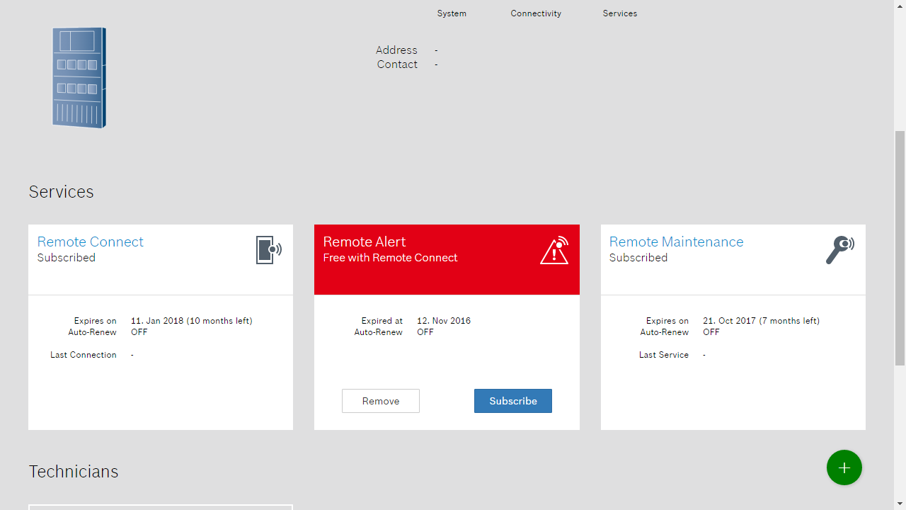
Remote Connect is the basic connectivity service provided by the Remote Portal which establishes a connection between system and cloud. Connection status of connected systems is automatically monitored and displayed in the system hierarchy. Additional information specific to systems is provided in later sections.
Customer access
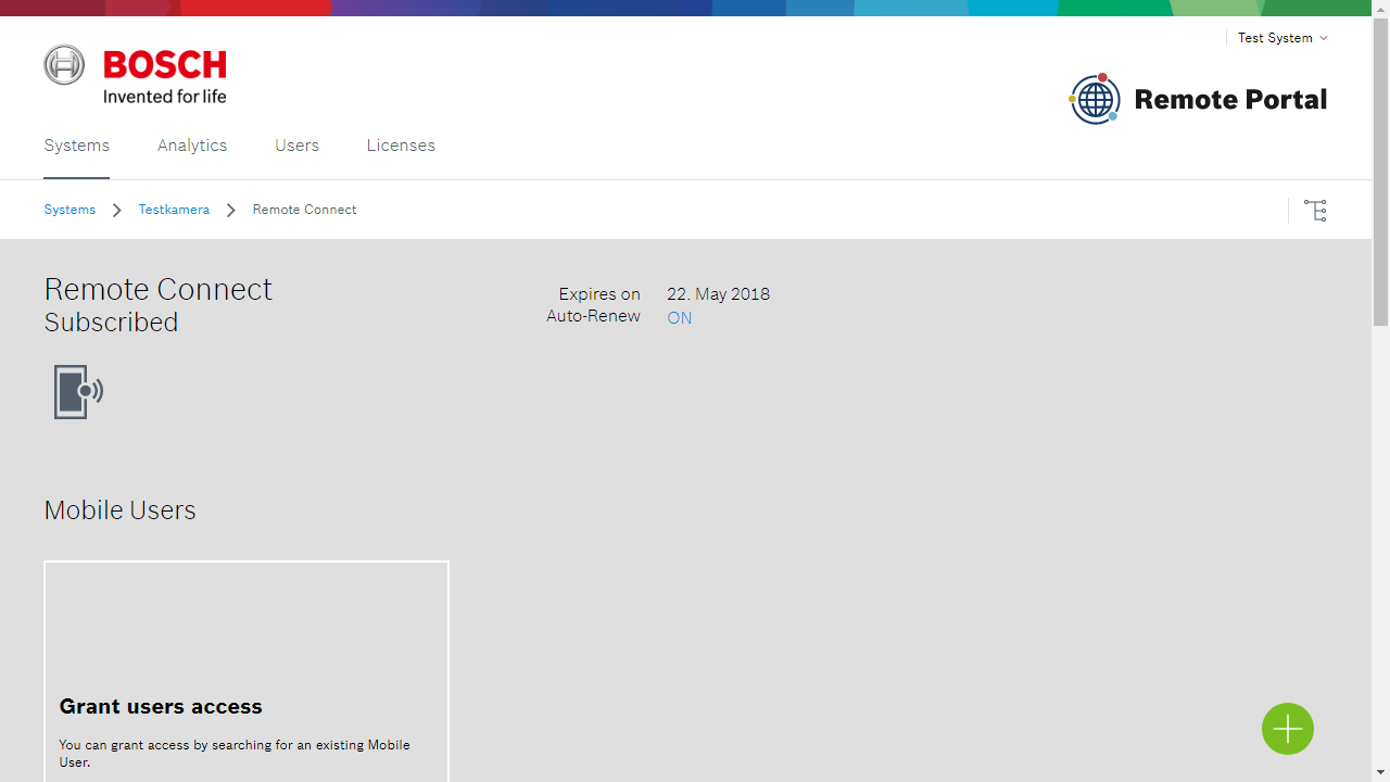
Connections using client software can be managed by adding "Customer" account to the Remote Connect service of a system. Customers can access devices using client software or via the Remote Portal (in scope limited to viewing of e.g. camera counter reports).
To add a "Customer" account navigate to the Remote Connect service page of a system and select the green "+" button.
Note
Technician access is managed by means of the System hierarchy.
Additional services
Activation of additional services it outlined in the service description in later sections.
B-/G-series
Connection
B-/G series panels automatically establish a secure connection to the Remote Portal (when cloud connection is enabled in the settings menu). To register a panel with a Remote Portal account the panel must be activated from RPS by use of its "Cloud ID". The cloud ID is provided in barcode and readable form as a sticker on the panel. To utilize cloud connection with these devices you must sign up with Bosch's installer services at https://installerservices.boschsecurity.com.
IP cameras
Connection
IP cameras can be associated with a Remote Portal account through the device's configuration pages by selecting the Advanced menu of the Network section of the configuration pages. Connect the camera to your account by selecting "Connect ... " and providing credentials of an administrator or technician account.
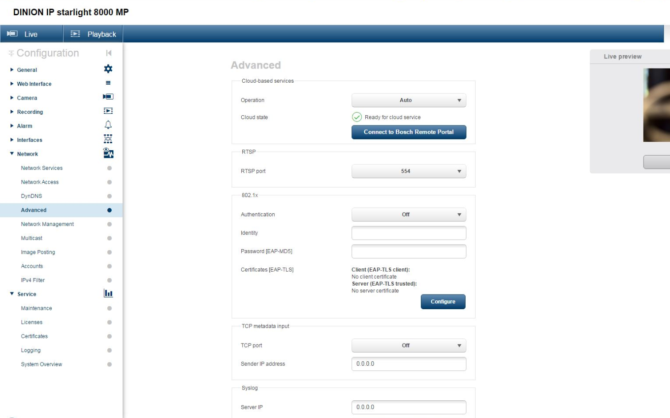
Note
Ensure that camera date and time are set properly. Otherwise connection with the cloud will fail.
Using a time server is recommended to ensure that camera time remains properly after initial connection. Consult the camera's manual on details how to configure a time server.
After registration on device visit the Remote Portal to configure access or camera counter reports.
Remote access
Administrators, technicians
Administrators and technicians can access the camera's configuration pages directly from the Remote Portal using the "Device page" link on the system detail page. Access via this link is authenticated by the cloud and connects to the camera with "service" level.
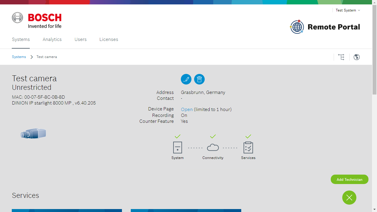
Note
Connections to camera BVIP pages are limited to approximately one hour. To start a new session reload the system detail page and open the "Device page" link.
Customers
Customers with access to an IP camera (assigned via Remote Connect) can access Camera Counter Reports or Camera Viewers. See the service description for more details.
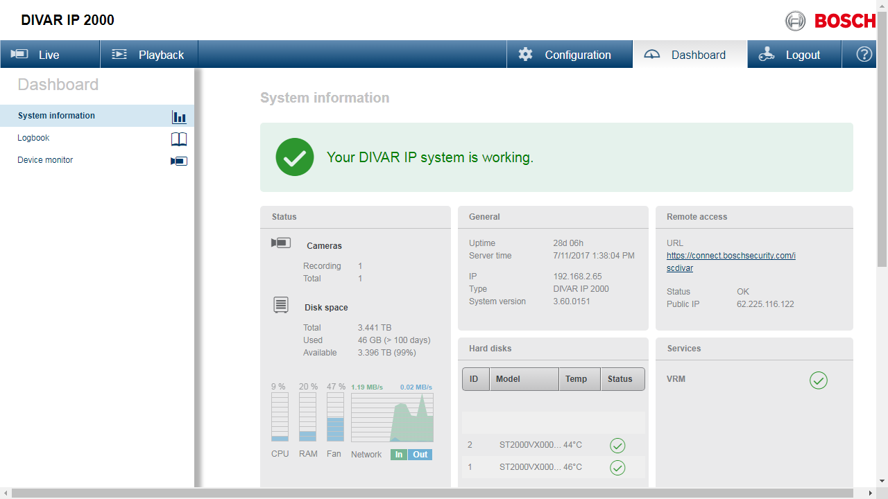
DIVAR IP 5000 (2000)
Connection
DIVAR IP 5000 (2000) can be registered with a Remote Portal account through the device's configuration pages, either as part of the setup wizard or (as shown) from the Remote Access section of the configuration page. Connect the DIVAR to your account by providing credentials of an "Administrator" or "Technician" account. The permalink URL allows logging into the device with local device credential at the selected URL.
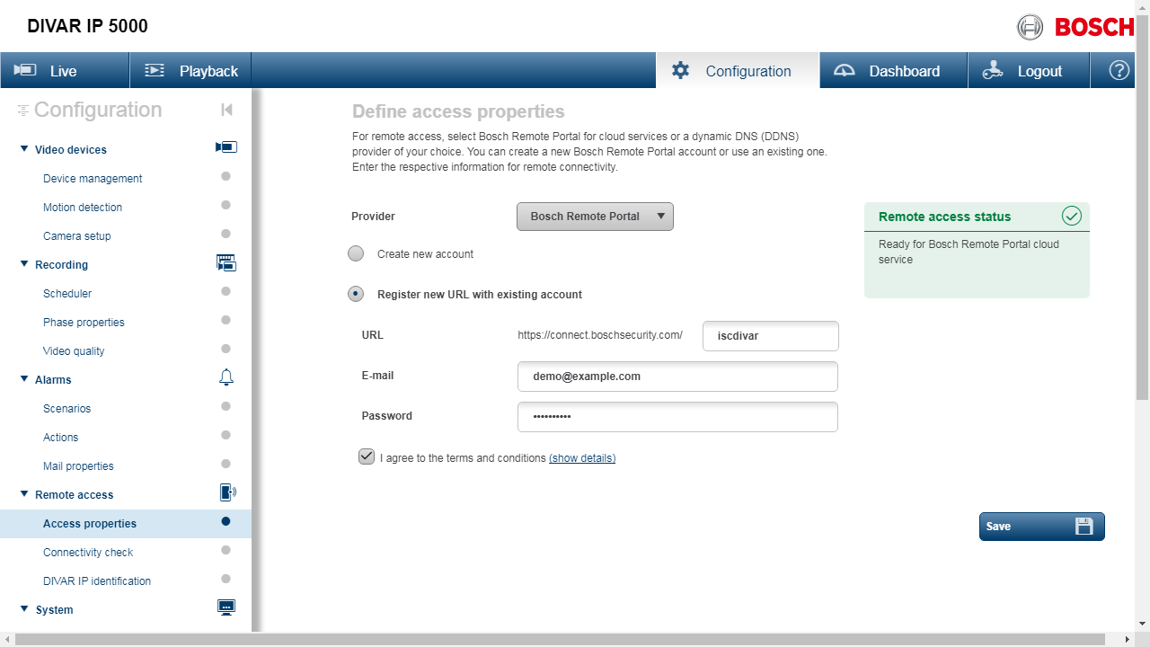
After registration on device visit the Remote Portal to configure Remote Connect for access using the Video Security Client or Video Security App (iOS).
DIVAR hybrid / network configuration
Connection
Full details on connection can be found in the DIVAR Operation Manual. To utilize Bosch Remote Portal follow these steps when configuring the device in the DDNS section:
Select the ‘Enable’ box.
Select Bosch Remote Portal as DDNS provider
Provide a unique name for this device. The domain "<name>.boschremoteconnect.com" will point back to the this device's public IP as long as the DDNS configuration is active.
In the account box provide "Administrator" or "Technician" credentials. For convenience a new Remote Portal account will be created for credentials that do not match an existing account.
Port forwarding
The access the system remotely the ports used by the apps must be forwarded to the system. This configuration is to be done on the network router that connects the local network of the recorder to the Internet.
It is recommended to forward the HTTPS, RTSP and TCP port and not the HTTP port for security reasons. The ports configured for these three services in the recorder settings need to be added to the port forwarding rules of the router pointing to the local network IP address of the recorder.
Remote Alert
Remote Alert monitors system health and allows sending of notifications (SMS, E-mail) to users based on configurable triggers. The table below summarizes available triggers and notifications types for different systems.
Remote Alert requires that Remote Connect is activated and available with a valid license for the system.
Intrusion Alarm System | Video System | ||||
|---|---|---|---|---|---|
Device | Triggers | Notification | Device | Trigger | Notification |
B-/G-Series |
|
| DIVAR IP 5000 (2000) |
|
|
DIVAR hybrid, DIVAR network |
|
| |||
IP cameras |
|
| |||
Note
Delivery of E-mail or SMS may fail for various reasons. Do not use Remote Alert applications for applications that require guaranteed delivery of notifications.
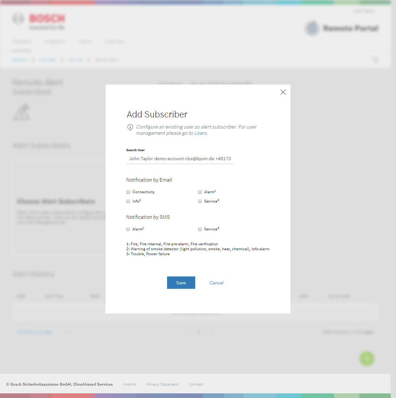
Configuration
Remote Alert is configured from the service detail page of each system. To start add a subscriber to Remote Alert using the green "+" button. Once a user is selected the Remote Portal will offer choosing the triggers and notification mechanism based on system type. The screenshot below is taken for a fire alarm system and varies slightly from other system types:
System specific notes
DIVAR IP 5000 (2000)
When enabling "Health Status" as a trigger for DIVAR IP the Remote Portal follows the overall status display of the DIVAR's dashboard. Notifications are sent when the dashboard changes from a green all-ok status to reported trouble.
DIVAR hybrid / network
"Health status" on these devices monitors whether the device regularly update its public IP address. The grace period between missed updates and sending of alarms can be 30 minutes or more.
FPA-5000
For FPA-5000 triggers for critical system events can send SMS and e-mail. The table below details which event classes exist and whether notifications can be sent via e-mail or SMS for this class:
Event class | Description | E-Mail notification | SMS |
|---|---|---|---|
Normal | ❌ | ❌ | |
Info | Warning of smoke detector (light pollution, smoke, heat, chemical), Info-alarm | ✅ | ❌ |
Service | Trouble, Power failure | ✅ | ✅ |
Alarm | Fire, Fire internal, Fire pre-alarm, Fire verification | ✅ | ✅ |
For each triggering system event only the initial trigger within a 24 hour period will be sent, this reduces the number of message in case of larger event bursts.
Furthermore the Remote Portal limits total amount of SMS to 10 per day, per account. The portal alert history however always show all events, independent of whether a message was sent or not.
IP cameras
When enabling "Health Status" as a trigger for IP cameras the Remote Portal will monitor changes of recording status for this camera. Changes to recording status trigger a notification.
Note
Recording status changes are monitored for SD-card, direct-to-iSCSI or VRM-based recordings. When using other recording solutions status changes may not be visible to the Remote Portal.
Remote Maintenance
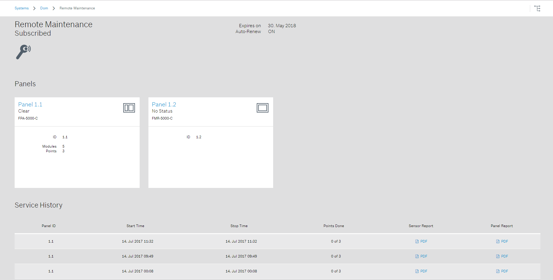
Remote Maintenance assists in performing maintenance tasks on compatible devices and systems. Remote Maintenance is currently available for FPA-5000.
System hierarchy and status
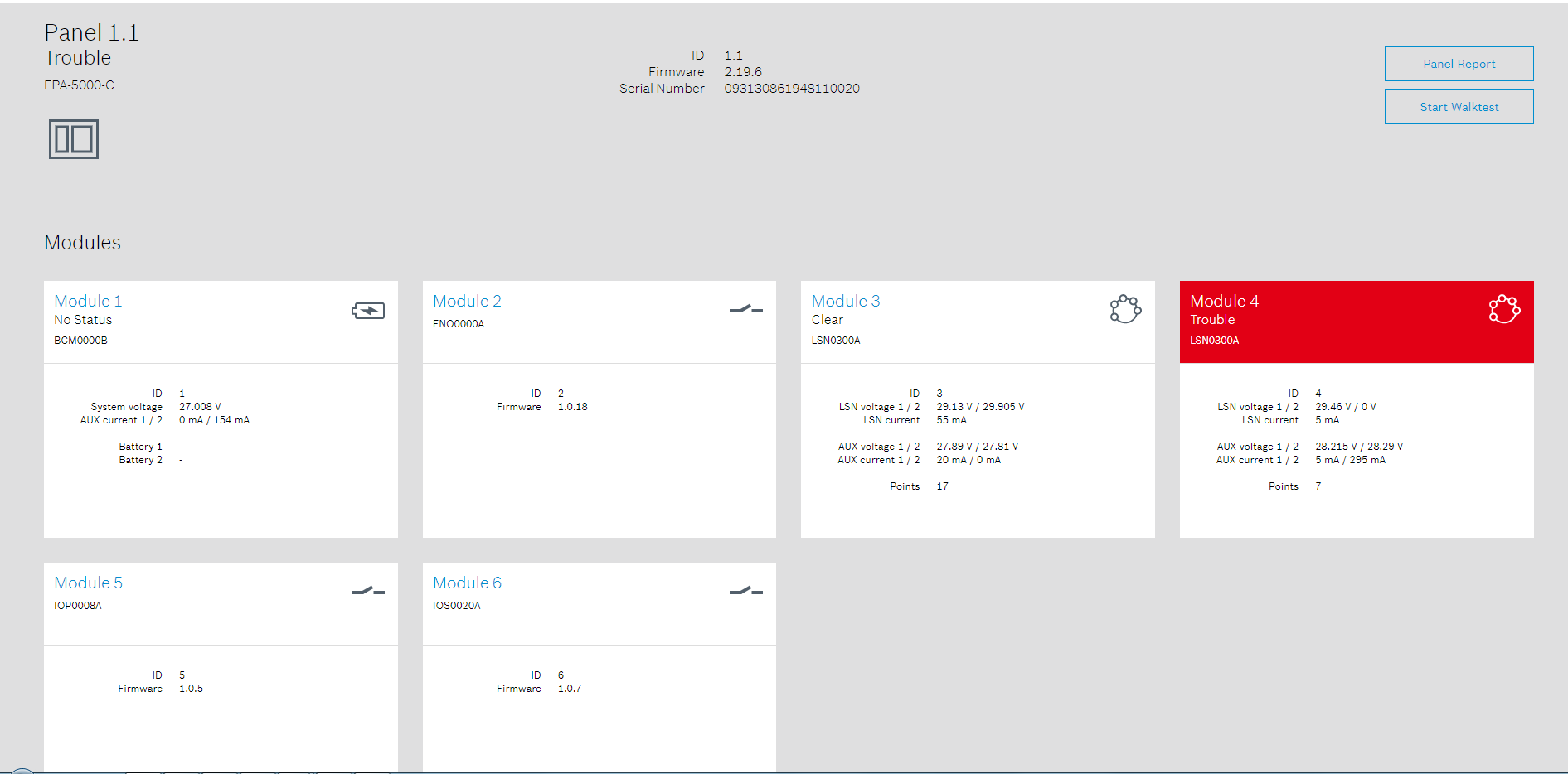
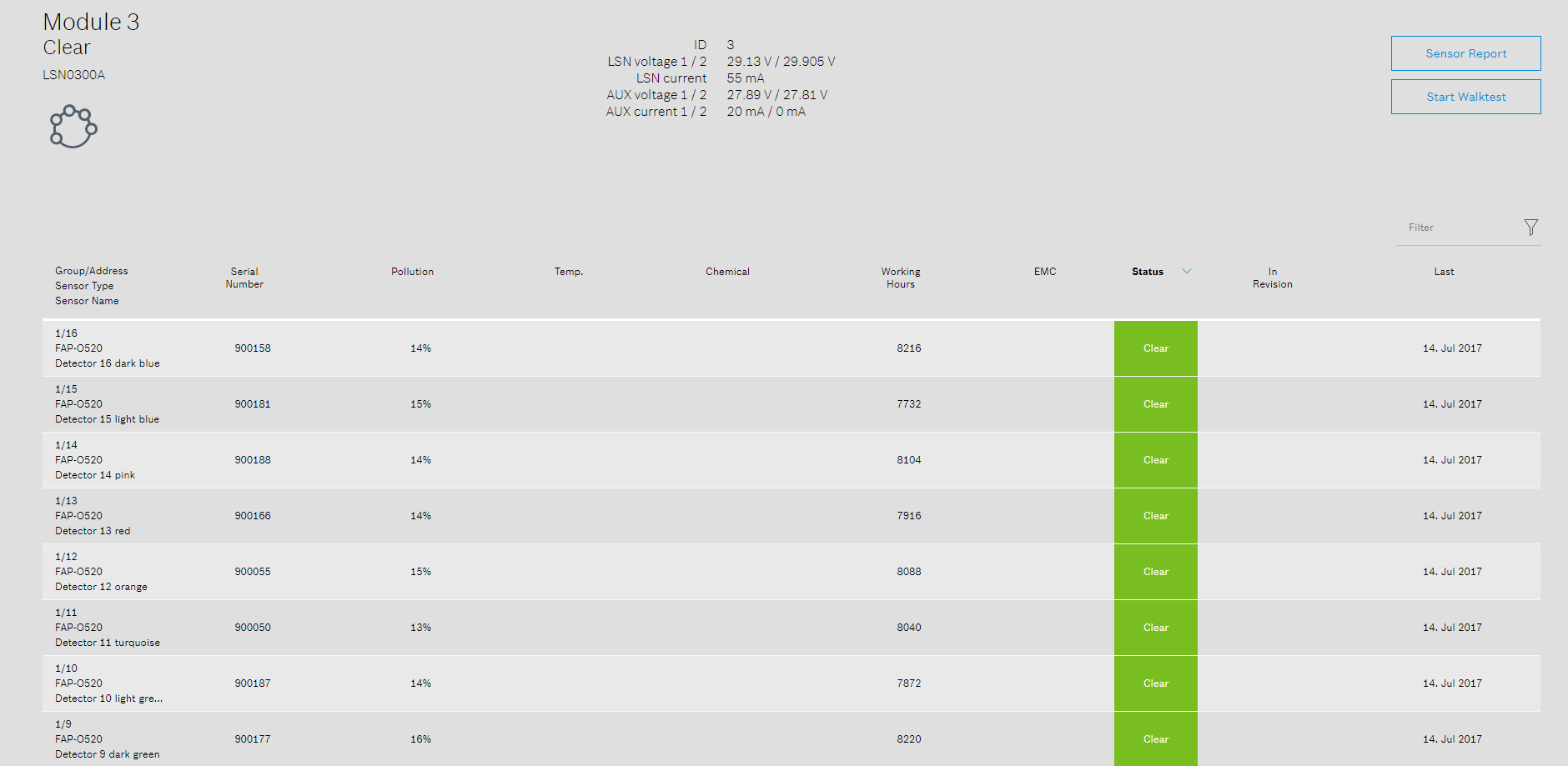
Remote Maintenance shows the complete hierarchy and status of a FPA-5000 system. The hierarchy is updated live from the system and lists all panels, modules and points as running on site.
For all panels modules and points of the system the Remote Portal displays status information (Clear, Attention, Trouble). To quickly judge the health of a system this status information aggregates from points to modules to panels, in this way a technician can see at once at top level if there are any issues for system components.
The status of a system can be exported to PDF by selecting panel report or sensor report from the respective pages.
Panel structure
Module structure
Point structure
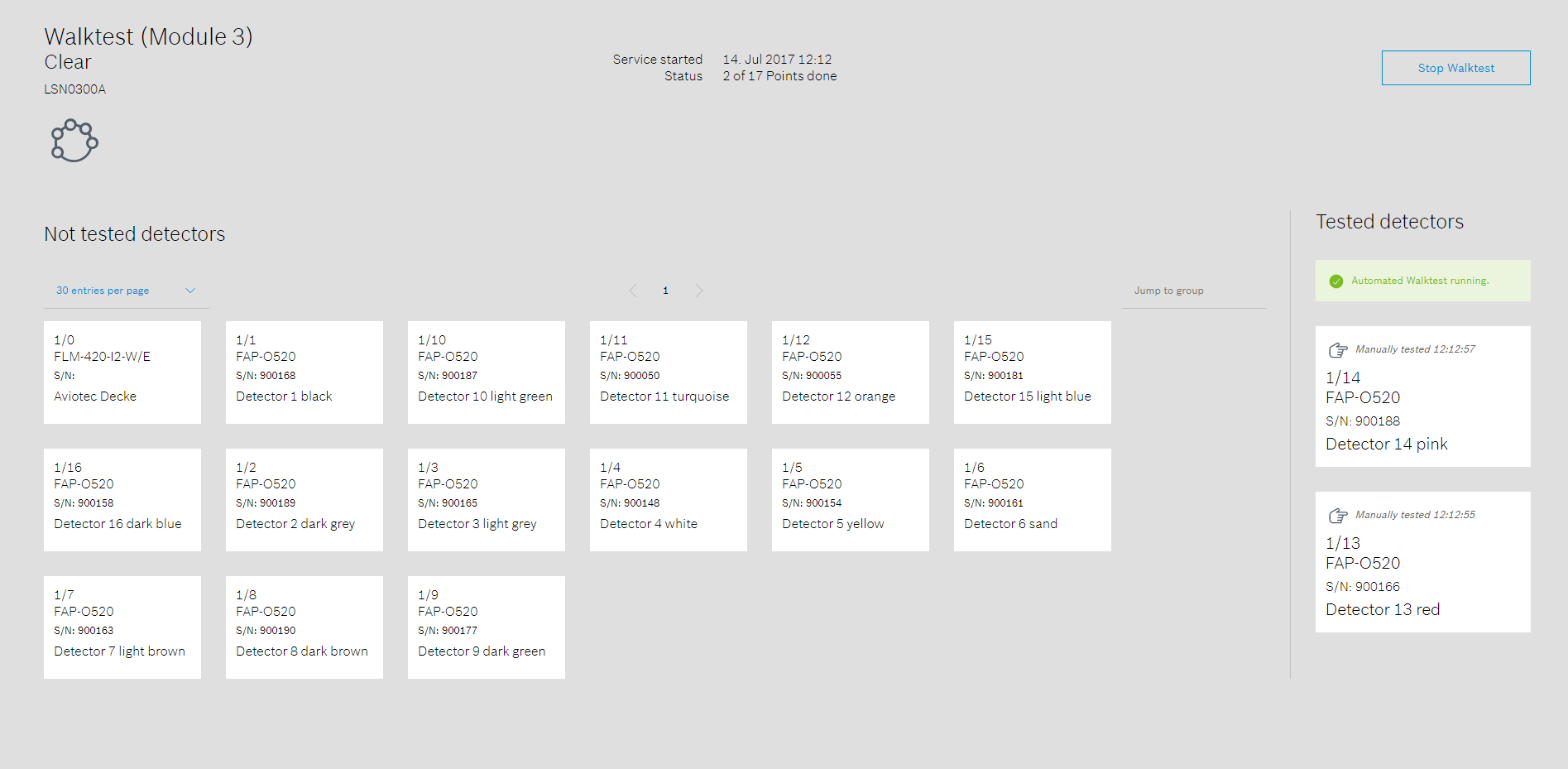
Walktest
The walktest service assists the revision on site. Walktests can be initiated either for a whole panel or for individual modules of the panel. When a walktest starts each point (e.g. smoke detector) is represented as a card. Cards put into revision mode are marked with a "R" and are ready for testing.
Cards are moved automatically from the left to the right side of the screen when the corresponding detector is tested successfully. This may take up to 30 seconds and requires that panel and mobile device are online and Remote Alert has been activated. If this does not apply, detector cards can be moved manually to the right pane by clicking on the cards. After finishing the revision a document is created and recorded in the history section and can be downloaded in PDF format.
Camera Counter Reports
General
Camera Counter Reports retrieve and store the values of camera VCA counters at regular intervals. The stored values can be visualized in the Remote Portal or exported to CSV files for further processing. Configuration of a report requires "Administrator" or "Technician" access to the Remote Portal and cameras to be used. Access to visualization and export can be granted to any customer.
Creating a Camera Counter Report uses one license, see Licenses for more details.
Configuration
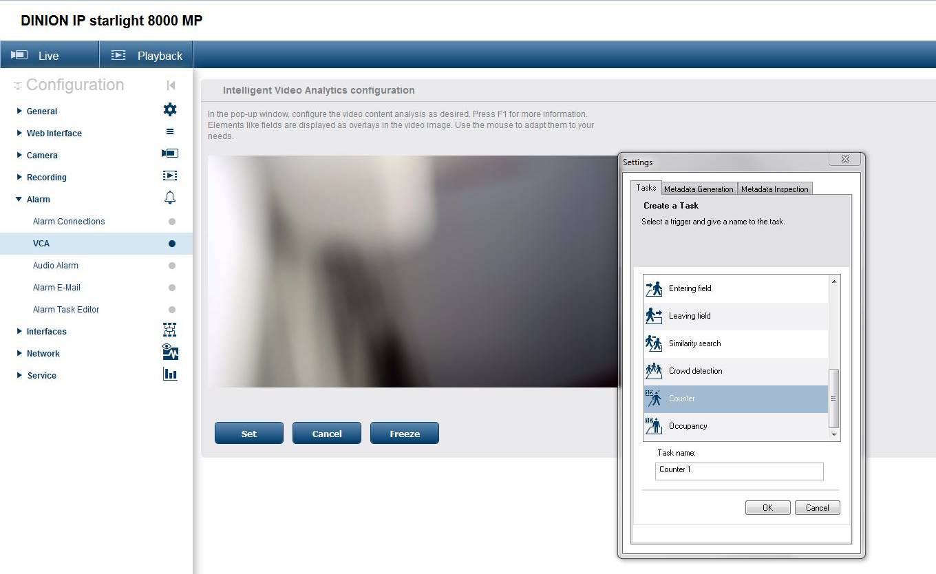
Camera configuration
Using cameras counters requires configuration of one or more VCA counting tasks on each camera. Follow the standard procedure for configuring cameras and setting up these tasks.
The task name given on camera will be used in the Remote Portal for configuration, preview or exporting.
Report configuration
Camera Counter Reports are created and configured from the Analytics tab of the Remote Portal.
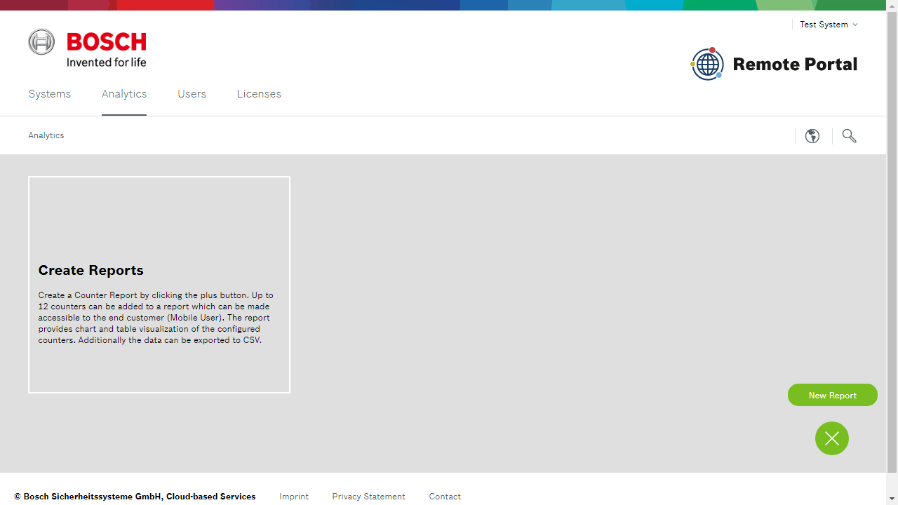
Select "New Report" and provide basic information as prompted:
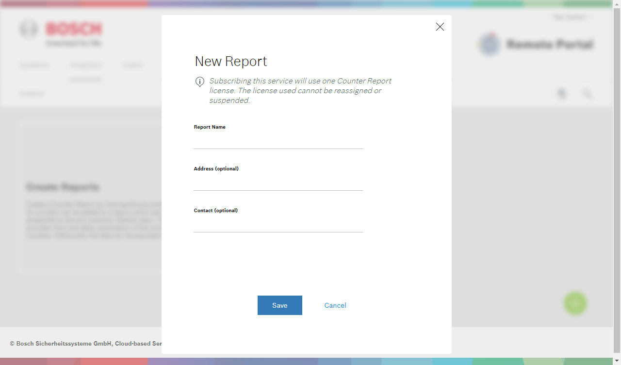
The first step after creating a report is to add cameras to the report. Press the green "+" button, select "Add camera" and search and select the camera by name or MAC address. The Remote Portal presents a list of counters that are available on camera, check each that you want to include in this report.
You can include multiple cameras in one report, up to a total of 12 counters.
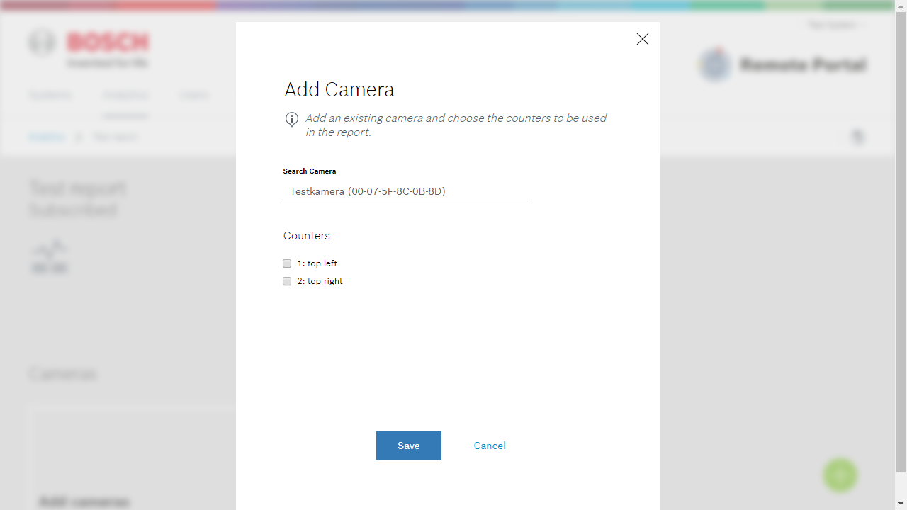
Note
Counter values are retrieved approximately every 15 minutes. Until first update cycle has completed both Preview and Exports will not contain any data.
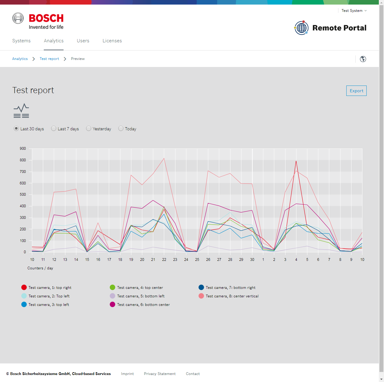
Preview
The Remote Portal provides basic visualization of collected counter data. For administrators and technicians this is available on the report's configuration page, for customers that where assigned the report directly from the start page after logging in.
Note
For display with hour resolution (yesterday/today) time is displayed in local time. For displays with day resolution the value displayed is the sum value of this day.
Export
Select the "Export" button from the top right corner to export data in CSV format. Export always exports all available data.
Note
Timestamps in exported data are always in UTC time zone. If required this can be changed to the proper time zone in post-processing.
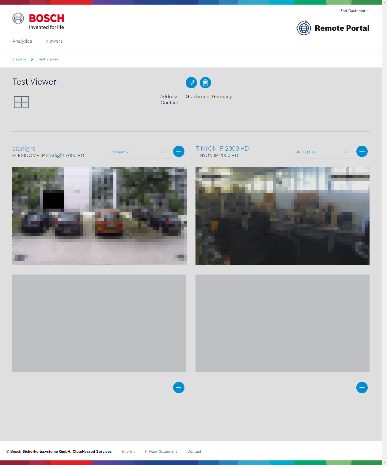
Camera Viewers
General
Camera Viewers are a light-weight viewing tool that give end customer browser-based access to live images and video streams of cameras. Up to four cameras can be displayed with live streaming or JPEG polling.

Configuration
Camera Viewers are configured by end-customers from the "Viewers" tab of the Remote Portal. A new Camera Viewer can be created by selection the green "+" button and providing a name for the Viewer.
.png?inst-v=351b8a5d-2311-4dca-936f-5d1e8b7ab61e)
Once a viewer is created cameras can be added and removed directly from the viewer itself. Note that a Customer is only able to cameras which are actively subscribed to Remote Connect and for which the "Customer" account has been attached to the Remote Connect service.
The screenshot below shows a Viewer configured with two cameras. Additional cameras could be added to bottom two grid positions by use of the blue "+" buttons, the top cameras could be remove by using the blue "-" button.
Note
Camera Viewers are configured per customer and cannot be shared between multiple customers
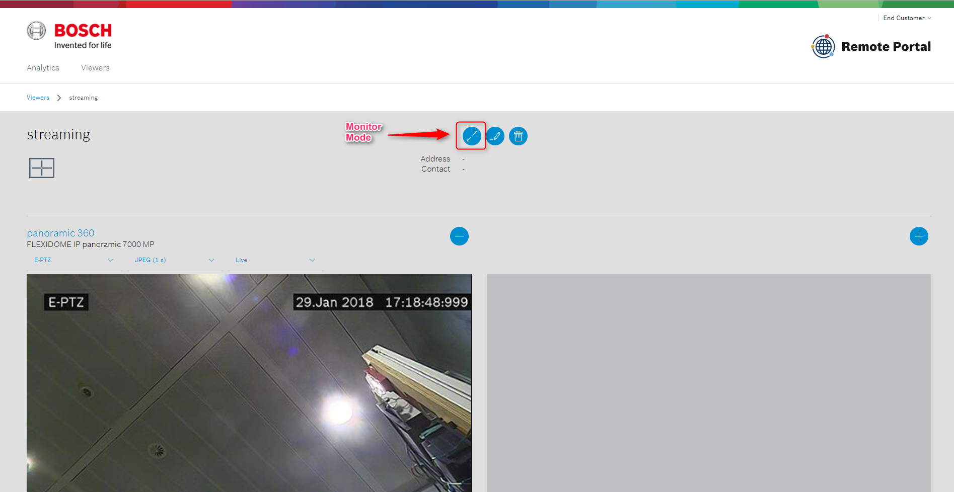
Usage
Camera Viewers are accessed from the Remote Portal using the Customer account used for configuration. For "viewing only" the viewer can be put into monitor mode which removes most of the controls and maximizes the display size of images and videos. In monitor mode three different layouts can be configured: grid view, focus view and single view.
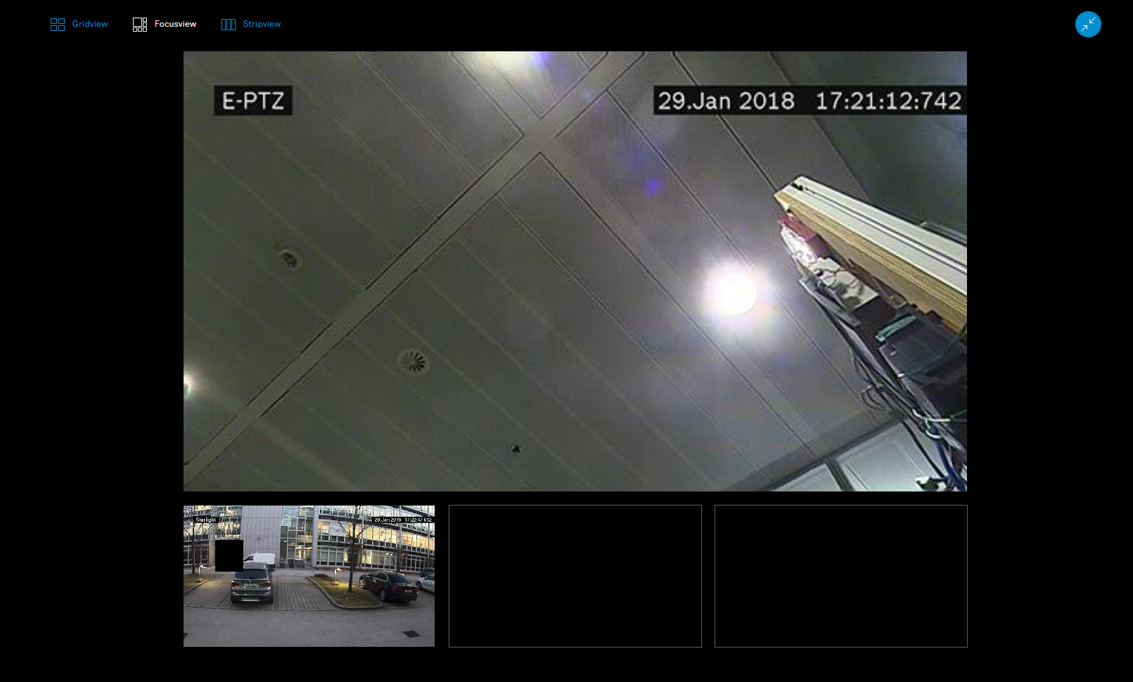
Note
Camera Viewers display images and video streams via the cloud, even if the viewer is used on the same network as the cameras. For local applications installation of a desktop viewer such as BVC or Video Security client avoids consuming bandwidth on the Internet uplink or issues due to bandwidth fluctuations.
5. Video systems
Compatibility
The table below lists software clients that are compatible for use with the Remote Portal managed users. Note that clients not listed may still be used for e.g. direct (local) connections but must configured individually.
Client | Platform | Compatibility |
|---|---|---|
Video Security App | iOS | DIVAR IP 5000 (2000) |
Video Security Client | Windows | DIVAR IP 5000 (2000) |
Configuration
Video Security App
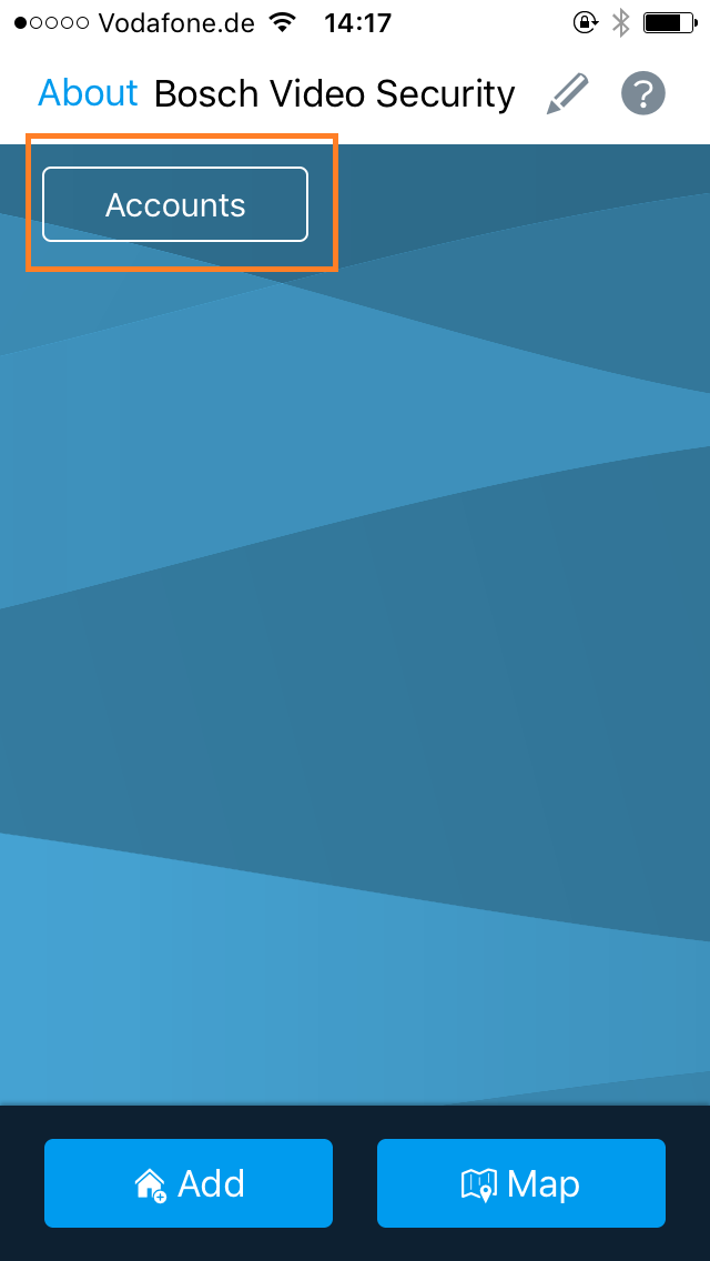
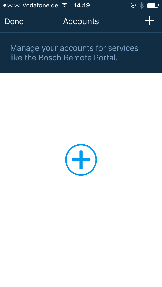
Download the "Video Security" app from the App Store and launch it. To establish connection to the Remote Portal select "Accounts" from the top left corner and tap "+" on the next screen:
Provide Remote Portal credentials (Administrator or Customer) on the next screen. Leave "Service address" unchanged.
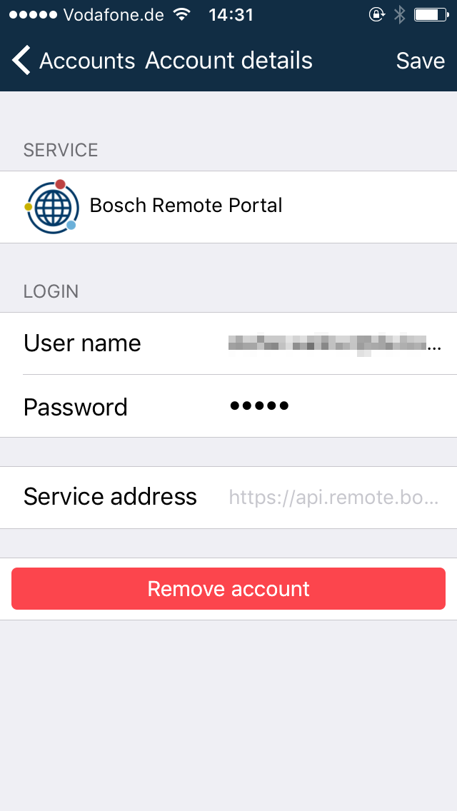
Select "Save". All devices that are accessible with the credentials provided will now be shown on home screen of the app and are ready for use.
.PNG?inst-v=351b8a5d-2311-4dca-936f-5d1e8b7ab61e)
Video Security Client
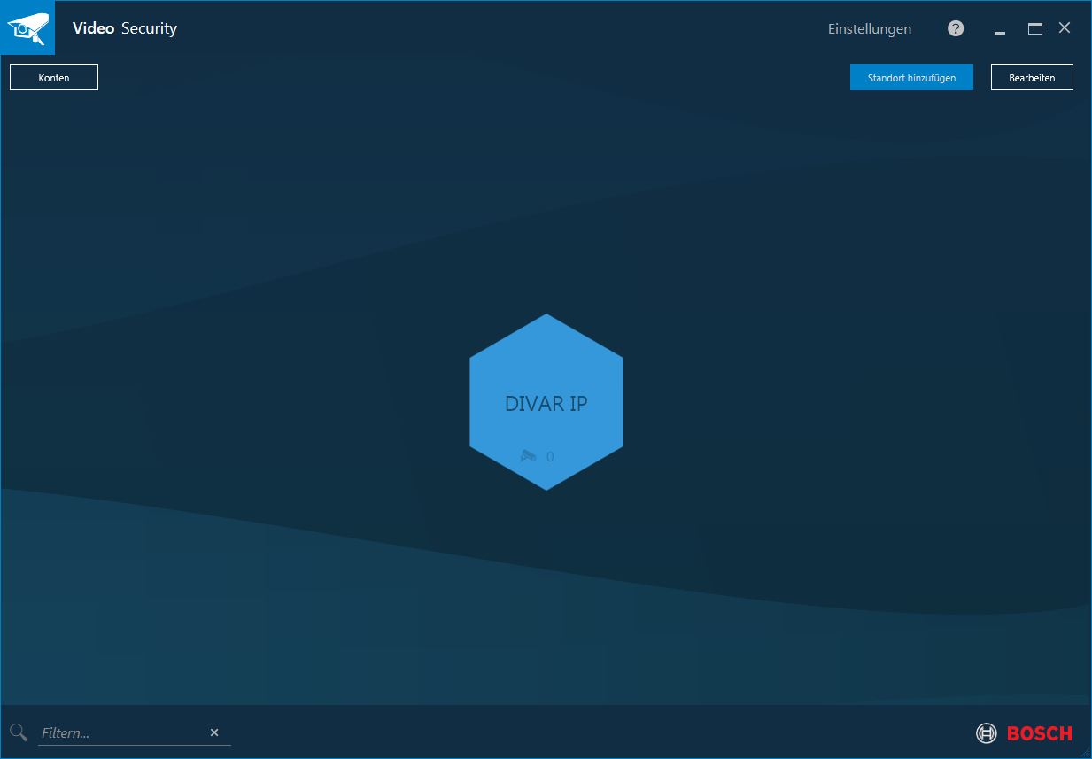
Video Security Client is available from the Bosch Download Store at https://downloadstore.boschsecurity.com. Select "Video Security Client" from the "Product Group" and download a suitable installation package. Install and launch the Video Security Client.
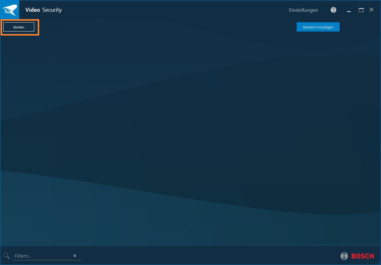
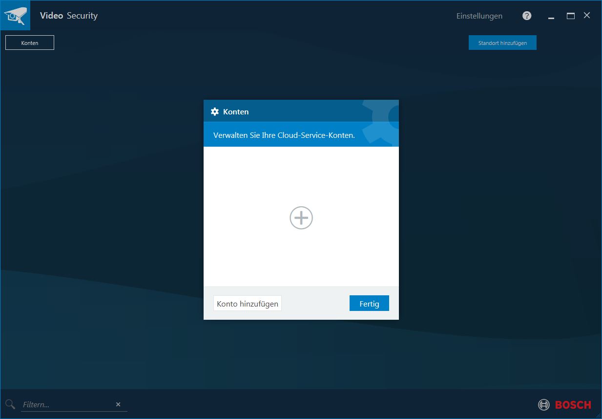
Provide Remote Portal credentials (Administrator or Customer) on the next screen. Leave "Service address" unchanged.
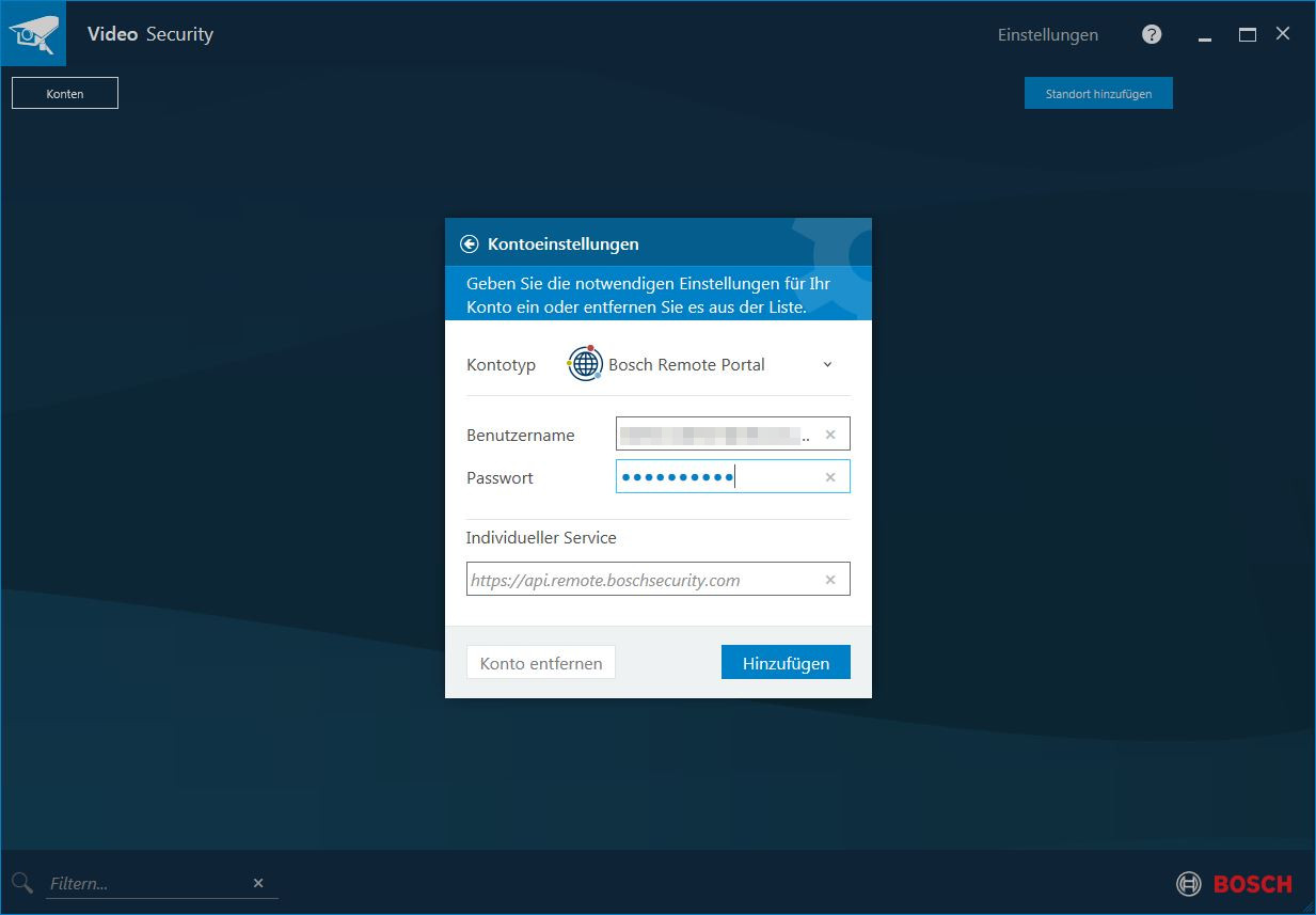
Select "Add". All devices that are accessible with the credentials provided will now be shown on home screen of the Video Security Client and are ready for use.